About a year ago, FlySorter took on a consulting project for the Klein Lab at the University of Miami, in Florida. Mason Klein uses Drosophila larvae to study biophysics and neuroscience, often with the same simple setup: a sheet of agar gel and a camera.
The Klein Lab records videos of freely wandering larvae on a bed of black agar and then analyzes their behavior. The duration of the videos is limited by the size of the agar gel — when the larvae reach the edge of the sheet, their behavior is impacted (or they either crawl off altogether) — and for 3rd instar larvae on a 10″ square sheet, it can be as quick as 10 or 15 minutes. We came up with the idea of using a robotic gantry and custom-designed nozzle to pick up larvae that had gotten close to the edge, replacing them near the center of the gel and thereby extending the experiments.
To cut to the chase: FlySorter successfully built a robotic system to relocate larvae on the agar bed for a total budget under $15k (for both time and materials).
I had experimented some already using a nozzle and vacuum to move adult flies around, but the first order of business for this project was to test something similar with larvae. Happily, it wasn’t too hard to pick them up off a bed of agar, but later, we’d discover the challenge of replacing them without having larvae stick to the nozzle or get blown away (by positive air pressure). Initially, I used a small, 3d-printed Venturi tube to generate the vacuum from positive pressure, but ultimately used a manifold that had separate air and vacuum inlets, and connected the robot to positive- and negative pressure valves in the lab.
For the actual robot portion of the system, we needed three full axes of motion. X and Y to access the extents of the sheet, and then a Z axis that could account for small differences in larva size (the 1st instar larvae are less than a millimeter in diameter, while the 3rd instar larvae can be almost 2 mm around) as well as any thickness variation across the agar bed (more on that calibration later). I opted to source an off-the-shelf X/Y gantry that was designed to drive a laser cutting head at up to 450 mm/s with sub-millimeter precision, and in theory, would save the time of designing my own, and possibly save some money on parts as well. In practice, I’m not 100% sure I came out ahead given the time it took to mount the gantry, connect to the various components (motors and end stops), as well as debug a handful of issues. Ultimately, though, it did serve its intended purpose of moving an end effector accurately around the workspace, and fairly quickly at that.
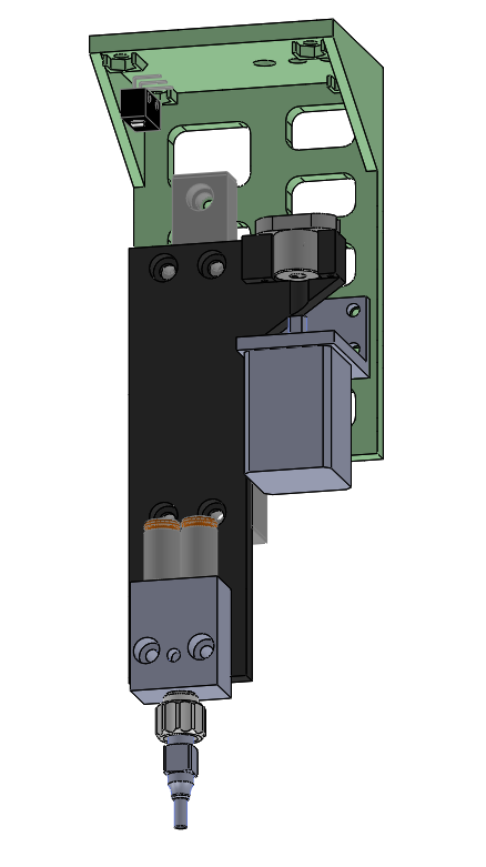
Our off-the-shelf options for a Z axis that fit the space, power, weight and cost constraints were essentially nil, so I designed a custom one instead. Space and weight were both a concern, and the forces on the axis aren’t high, so I chose a small, NEMA-8 stepper motor as the actuator. Since the total travel wasn’t very long (around an inch or so), I chose a small linear bearing from McMaster as a base for the motion, and a lead screw / nut combo that would give sufficient accuracy without limiting speed. A handful of 3d printed parts made the connection between the motor, lead nut, slide, air/vacuum manifold, and nozzle.
I opted to use the venerable SmoothieBoard for motion control. It was originally designed as a control board for 3d printers, but its robust firmware can be easily configured and extended to serve other purposes. In short, it provides a USB control port that “speaks” G-code, and beyond stepper motor interface chips, also has a set of load switches (MOSFETs) that can turn on and off devices such as LEDs or solenoid valves, all controlled programmatically. It’s easy to communicate from a PC to the SmoothieBoard via a Python script, and there are plenty of programs available for testing and debugging the system, since it looks quite similar to a 3d printer from the computer’s point of view. To boot, the Smoothie team is very responsive when it comes to any sort of issues. I’m a big fan.
Here’s what the robot looks like:
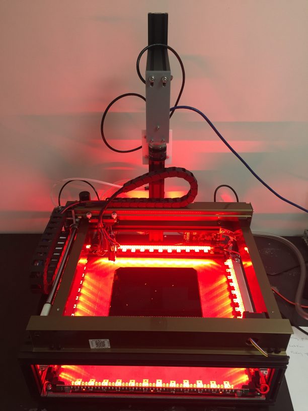
The agar bed is the black square with white larvae crawling on it. The larvae are edge-lit by red LEDs (they don’t see the color red, so the lighting doesn’t affect their behavior), and the camera is mounted on a bracket above the robot. The X/Y gantry remains at the back of the robot when not actively repositioning larvae. Also visible at the back of the robot are some of the air and vacuum tubes, which run through the cable chain to the end effector. Just out of view on the left-hand side of the robot is the power supply, and the control board is mounted on the rear, right-hand side of the frame.
By far, the most challenging part of this project was the nozzle. Even with our initial testing, the design and validation of the larva nozzle, along with the associated plumbing and control software, took quite a bit of time. As previously mentioned, picking them up was relatively easy, but it took many iterations to find a material that larvae wouldn’t stick to, and ultimately required some new programming tactics as well. I tried 15-20 different nozzle prototypes, and the final version is made from a short, stainless steel blunt needle partially plugged up with bent aluminum wire (top, center in the photograph below).
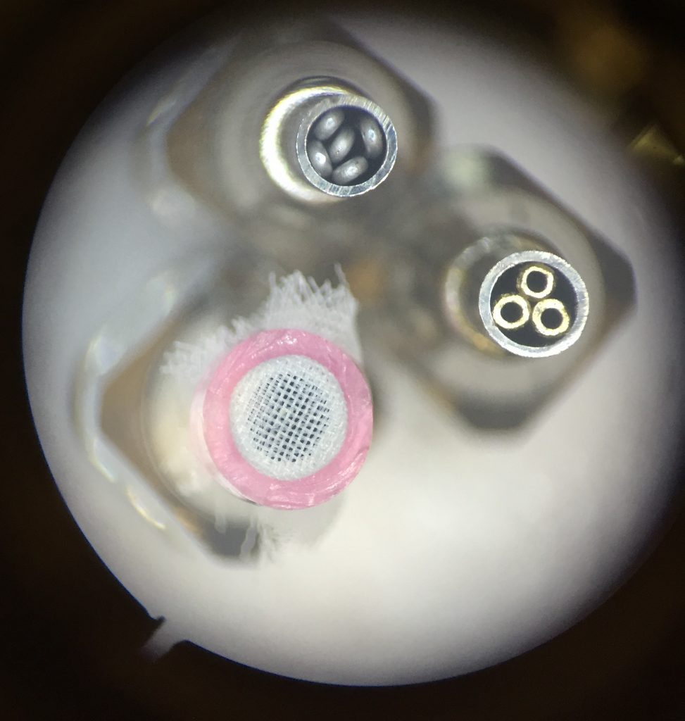
To release the larvae, we knew we couldn’t rely on just turning off the vacuum; we had positive air pressure available as well to push the organisms off the nozzle. Too little air flow meant the larvae would remain stuck to the nozzle, and with too much air pressure, and the larvae became projectiles. The trick was not only finding the right air pressure but also positioning the nozzle so the larva was touching the agar (just barely) in its final location. Surface tension helped prevent flying larvae. Ultimately, I added adjustable flow valves for both the positive and negative pressure air lines for fine control, and the manifold on the end effector includes a pressure sensor (connected to an analog input on the SmoothieBoard) so settings are repeatable.
There are quite a few components that comprise this system, and each needs to be precisely calibrated to the next to ensure accurate sensing and positioning. For reference, the smallest (1st instar) larvae are smaller than a grain of rice, the diameter of the nozzle is only 3 mm, and the larvae are awake and moving, so by the time the camera has captured an image, the computer has calculated the larva’s position, and the robot has moved there, the organism is actually a little bit displaced. The first source of inaccuracy I corrected was between the SmoothieBoard and robot. I commanded the robot to move 100mm, say, in X, and then measured the actual movement. Any difference was accounted for in the “steps-per-millimeter” setting in the configuration. Ditto for Y and Z. Next, I addressed any variation in thickness across the agar bed. There is a pressure sensor in the manifold, so I wrote a routine that turns on the vacuum and probes the bed in a few places, using the pressure to detect when the nozzle had touched the agar. Finally, I needed to connect coordinates in the images captured by the camera to the robotic coordinate system. I wrote another script to move to known X/Y locations and deposit 3d printed calibration discs. When the robot has placed the last disc, it moves out of the way and the camera captures an image:
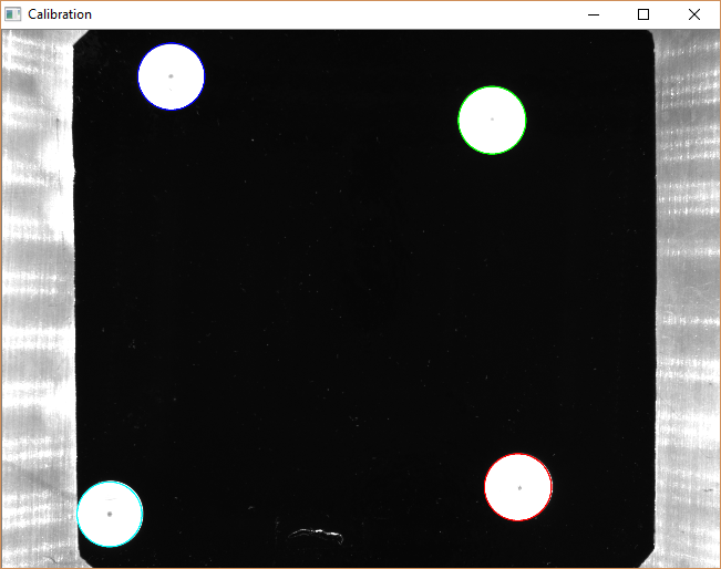
The script then detects the location of the discs and calculates the transformation (a homography) between the image coordinates and the robot coordinates. It’s important that the calibration points are located on the agar surface, otherwise parallax error creeps in and causes the robot to miss larvae.
The final piece of software is a Python script that “watches” a designated image file. When that file is updated, the program looks in the image for larvae around the edge of the agar bed. If any are found, the program directs the robot (by way of the USB connection and G-code commands) to pick them up and replace them in open spaces near the center of the bed.
Here’s a video of the robot in action, picking up and redepositing a larva, after it’s been calibrated:
FlySorter is always happy to discuss custom projects, large or small. If you’d like to bring robotics or automation into your fly lab, drop us a line!
[ The software for this larva robot is available on Github, and is distributed under the GPL v3 license (usable and shareable by all). Hardware files coming soon. ]